We were recently contacted by the photographer Francesco Conti and the graphic-designer Stefania Servidio, founder of Agency for disasters, asking for help on realizing the electronics part for the Mayan prophecy 2012 ® installed on the final Prize of the Italian Premio Celeste 2012, a well known context promoting the Contemporary Art in Italy. We liked the idea and we decided to support the project realizing a stand alone, Arduino based, digital countdown timer.
Requirements were defined since the beginning: he asked for realizing, in a relatively short time of about 15 days, an electronic circuit able to count days, hours, minutes and seconds to the Mayan Prophecy. The required display dimensions was something in between 35cm by 3cm. The display should be realized with red LEDs and the circuit will be powered up by a switching power supply.
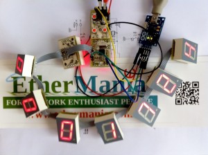
We opted for a solution based on a set of shift registers driven by an atmega328 microcontroller. Each shift register is able to drive a single LED digit and is connected to other digits through a 5 wires flat cable. This architecture allows the author to easily place each digit into the opera and allow us to minimize problems could happens in the development time. Each digit is an easy to replace circuit connected to each other between 5 wires: two for the 5+ supply, one for the clock, one for the shifted data and the last for the strobe.
We opted also to adopt the open source philosophy and we decided to release schematics and firmware publicly available at the EtherMania GitHub repository under the Creative Commons Attribution-Share Alike 3.0 Unported Licence.
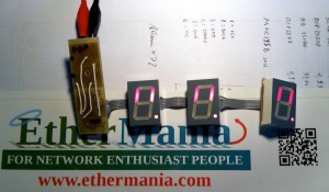
To limit the overall circuit dimensions and the implementation time we opted to realize a set of PCBs, one for each digit, where the display and the related shift register should be assembled. Each PCB is connected to the next digit through a set of connectors. The most significant digit counting the day is the only one directly connected to the atmega328. We opted to develop a special PCB for that and we were able to place three push buttons (to be used to setup the time) and headers for connecting the PCB to a Serial2USB converter. This converter allowed us to connect the overall display to the Arduino IDE (we programmed an Arduino bootloader on the atmega328) and program it like if we were in front of an Arduino UNO.
Here are some pictures taken on the different steps of our job.
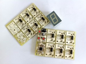
We panelized the single digit PCBs. We were able to have 6 shift register based digits plus one atmega328 based digit for each EuroCard PCB. We manually assembled the PCBs.
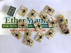
PCBs were after separated.
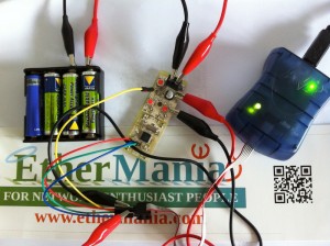
Than we programmed the Arduino bootloader on the atmega328. The green LED on the programmer shows that all is properly working!
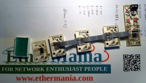
Each digit is then connected through a flat cable.
We decided to test each new digit added. This was useful to find some short-circuits caused by the SMD manual assembly.
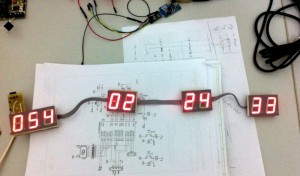
Then we started to program the firmware. The display is connected to an USB2serial adapter that, interacting with the bootloader, presents the unit to the Arduino IDE like if it is an Arduino UNO board.
We ended up to couple together some digits with strips of adhesive tape.
The firmware implementation was a very pleasant experience. We mainly wrote the software in the period we were waiting for the PCB production, then it was modified to adapt it to the final system. We used a lot of C++ so we were able to emulate in software the same architecture and logic we have in the hardware. The “Display” type, defined as an object able to render a single digit, was encapsulated in a interface then inherited by two different implementations: the shift-register based and the latched based digits. The specialized objects transparently handle the communication layer so the main program “forgets” about latched and shift-register based digits.
Here is a summary of what the system is able to perform:
- Very lite system based on atmega328, programmable through the Arduino IDE and compatible with the Arduino framework
- “MODE” push button for the operation mode selection: run or setup
- “UP” push button used to change the digit value (in setup mode) or to cycle through four different display brightness (in run mode)
- Countdown till the value 000:00:00:00 then countup
- Count up/down selectable in setup mode

